GPIO Pinout
GPIO stands for General-Purpose Input/Output. It is a feature of many microcontrollers and microprocessors that allows them to interact with the outside world. GPIO pins can be configured as inputs or outputs, and they can be used to connect a wide variety of devices, including sensors, actuators, and LEDs.
A GPIO pinout is a diagram that shows the location and functionality of the GPIO pins. It is always a good idea to consult the GPIO pinout of your card before you start working on your project.
You can also use this command on Raspberry Pi OS:
Raspberry Pi 1B+, 2, 3, 4 and 5
The Raspberry Pi has 40 GPIO pins organized into two rows of 20 pins each. The pins are numbered from 1 to 40, with pin 1 being in the top left corner of the board. The pinout also shows the functionality of each pin, such as whether it is an input, output, or PWM pin.
Here is a table that summarizes the functionality of the GPIO pins on the Raspberry Pi :
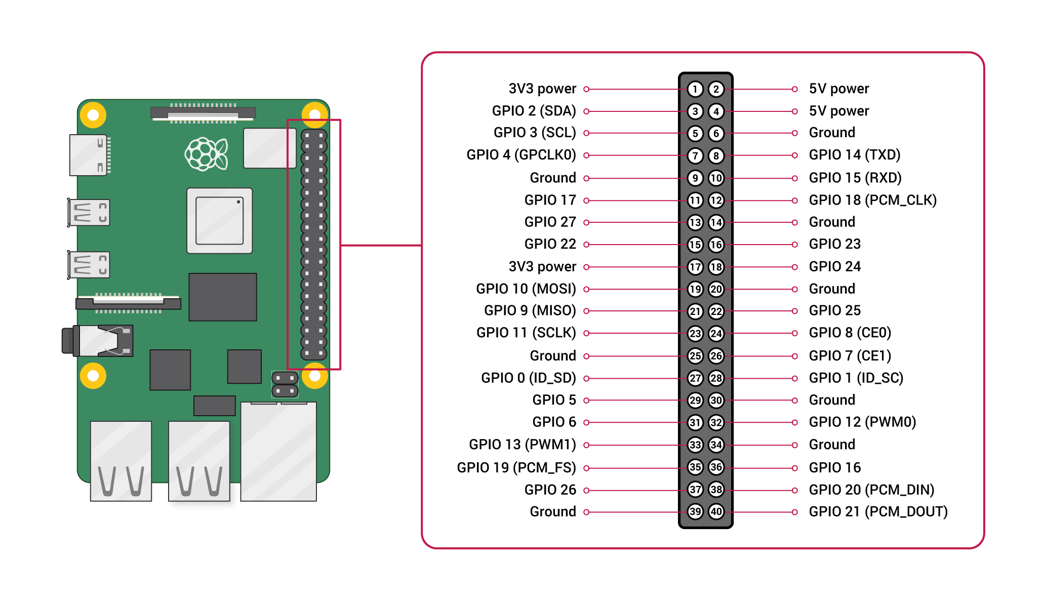
3V3 - Pin 1 and 17 This means 3.3 volt. The 3V3 pins can be used power low energy consuming parts, like a couple of LED's. Never use more than 50 mA, so for example no more than 2 LED's.
5V0 - Pin 2 and 4 This means 5.0 volt. The 5V0 pins can be used to power more energy consuming parts, like more LED's, a small motor, a servo, etc... The 5V0 pins can provide more, but this depends on the power consumption of the Pi itself, the number of USB devices that are attached and how much your mini-USB power supply can provide. Think about approximately 500 mA maximum.
GND - Pin 6, 9, 14, 20 and 25 The GND pins are ground pins. When you connect a power consuming device, you connect it between either 3V3 and GND or 5V0 and GND.
Raspberry Pi 1 26 pins
Voltage
Two 5V pins and two 3.3V pins are present on the board, as well as a number of ground pins (0V), which are unconfigurable. The remaining pins are all general purpose 3.3V pins, meaning outputs are set to 3.3V and inputs are 3.3V-tolerant.
As well as simple input and output devices, the GPIO pins can be used with a variety of alternative functions, some are available on all pins, others on specific pins.
- PWM (pulse-width modulation)
- Software PWM available on all pins
- Hardware PWM available on GPIO12, GPIO13, GPIO18, GPIO19
- SPI
- SPI0: MOSI (GPIO10); MISO (GPIO9); SCLK (GPIO11); CE0 (GPIO8), CE1 (GPIO7)
- SPI1: MOSI (GPIO20); MISO (GPIO19); SCLK (GPIO21); CE0 (GPIO18); CE1 (GPIO17); CE2 (GPIO16)
- I2C
- Data: (GPIO2); Clock (GPIO3)
- EEPROM Data: (GPIO0); EEPROM Clock (GPIO1)
- Serial
- TX (GPIO14); RX (GPIO15)
A handy reference can be accessed on the Raspberry Pi by opening a terminal window and running the command pinout.
Source
https://siminnovations.com/wiki/index.php?title=General_Raspberry_Pi_I/O_pin_explanation